What is a Programmable Logic Controller (PLC) and How it Works
A programmable logic controller is a device programmed to control certain processes in industrial sites, such as control of machinery on factory assembly lines, enabling industrial automation.
Industrial automation involves the operation of industrial machinery with little to no human intervention, machinery being given run and stop signals from PLCs and other industrial automation devices.
Before the era of PLCs, automation control tasks were mainly through contactors and relays. The use of contactors and relays is often called hard wiring.
With the increase in industrial automation, these contactors and relays are becoming bulky for just controlling even small processes, leading to difficulties in wiring the circuits and finding faults.
With hard wiring, if an error is made, the wires must be reconnected correctly. A change in the control or process expansion requires extensive rewiring and components changes.
The introduction of PLCs reduces the number of electrical wirings, and if changes need to be made, PLCs only need to be reprogrammed without the need for rewiring, enabling seamless automation in large industrial sites.
Programmable Logic Controller Parts
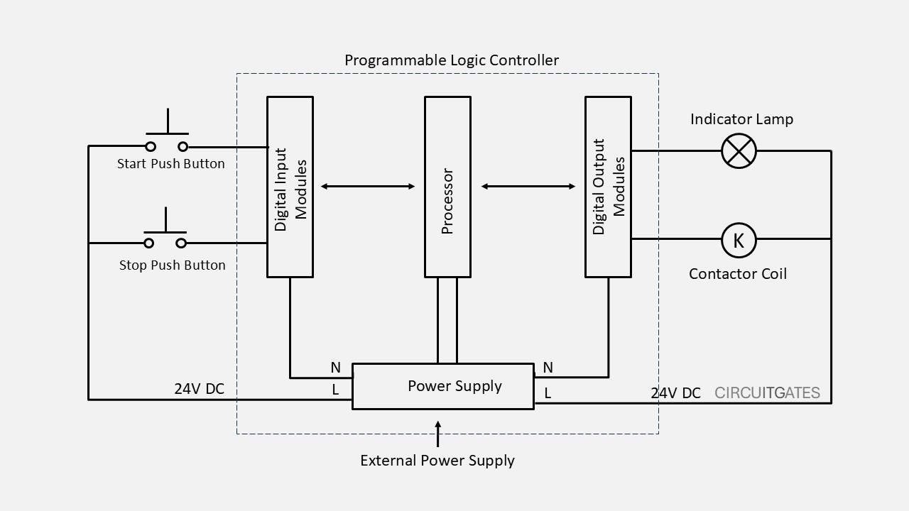
A PLC consists of the following parts: a power supply, processor (CPU), input modules, output modules, and a programming device
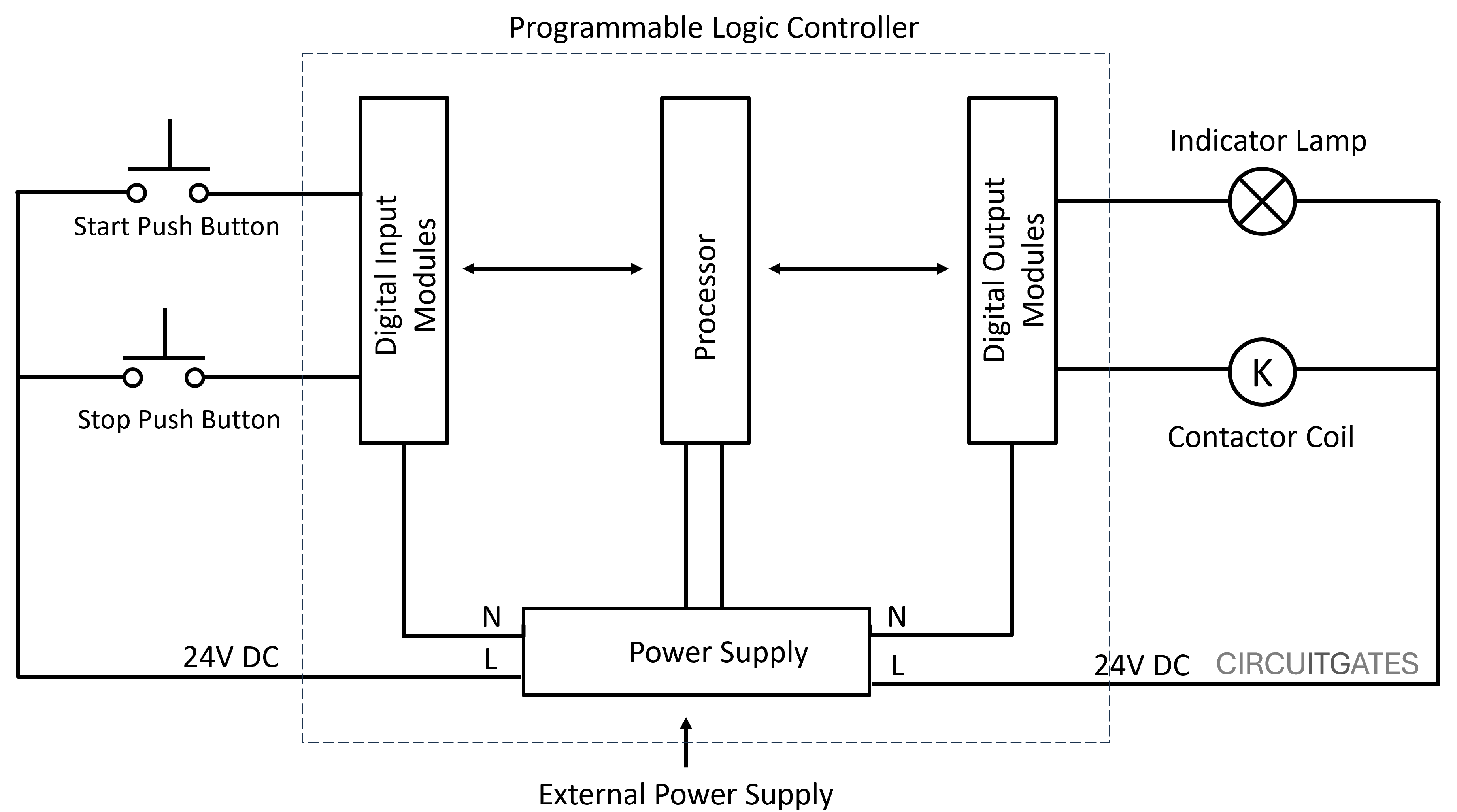
Power Supply
Receives power from the external supply and distributes it to the PLC components such as the input modules, output modules, and the processor.
The power supply also steps down the incoming AC voltage to a lower level voltage suitable for the PLC components and converts the stepped-down AC voltage to a stable DC voltage (e.g., 24V DC) required by PLC components.
Digital inputs and outputs of the PLC can work with either AC or DC, but other PLC components such as the processor, analogue inputs, and outputs work well only with DC.
Input Modules
Input modules are the part of the PLC where external input field devices such as limit switches, push buttons, sensors, and more are connected. Input modules receive signals from the field devices.
We have two types of input modules based on the type of signal they receive: analogue and digital input modules.
Digital Input Modules
These are input modules of the PLC that receive individual or discrete signals that can be either ON or OFF (0 or 1).
For example, when the field device wired to the input module, like a self-latching push button, is put in the ON position, current flows through the module, signaling an ON or 1 to the module, as in the following diagram.
A self-latching push button is a button that remains in the position you put it in after pressing it, like domestic lighting switches.
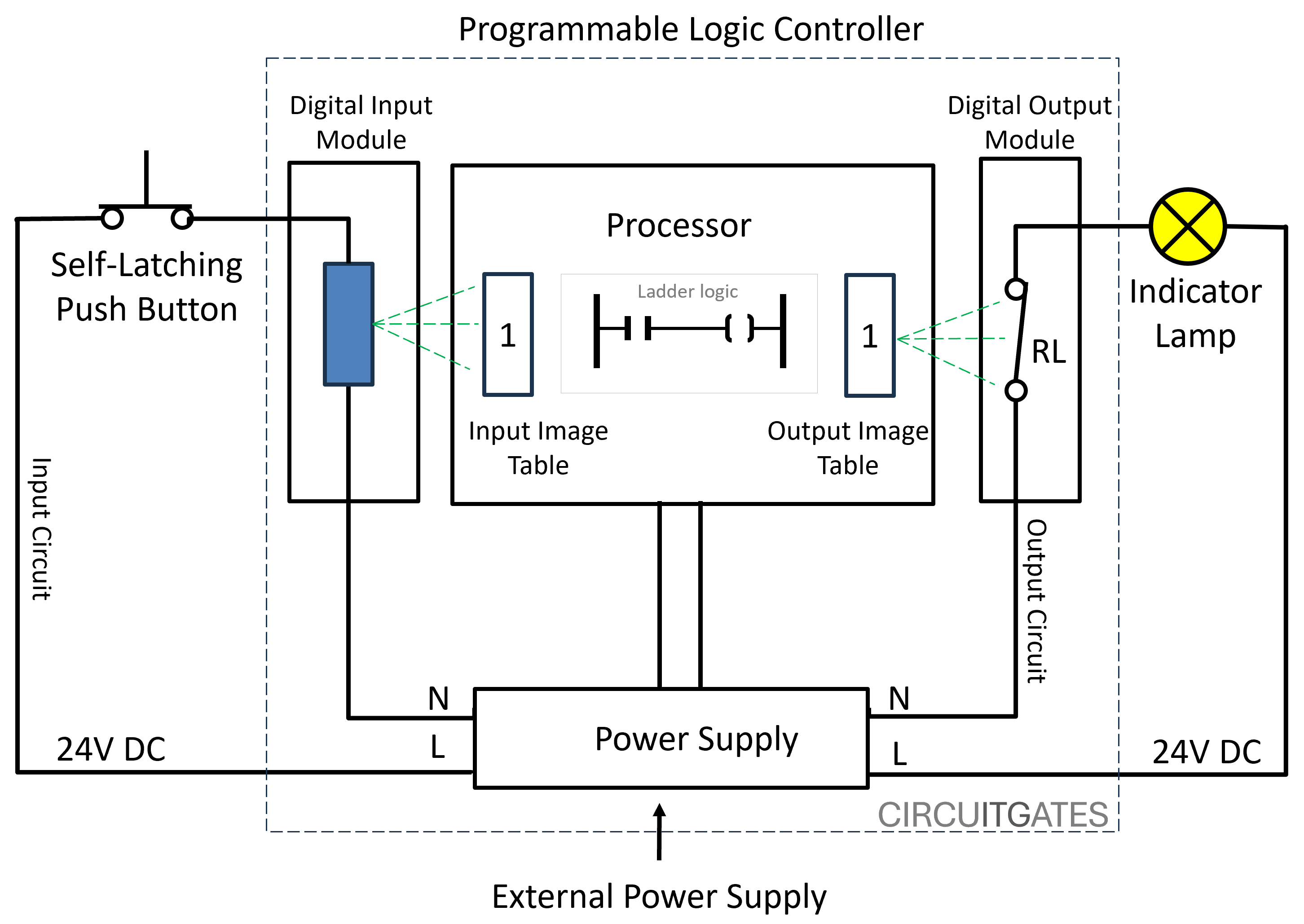
If the self-latching push button is put in the OFF position, there is no current through the module, signaling an OFF or 0 signal to the input module.
Analogue Input Modules
These are input modules of the PLC that receive continuous signals from devices like potentiometers and sensors. The continuous signals received by analogue input modules are usually in the form of current or voltage.
Since the input signal is continuous, a change in the parameter being monitored causes a change in signal value received by the input modules. These signals typically change within a range of values, such as 4-20 mA or 0-10V.
Since the PLC only understands digital signals, these analogue input modules will convert analogue signals to the digital signals that a processor understands.
Output Modules
Output modules are part of the PLC where external output field devices such as electric motor contactors, relays, indicator lamps, and more are connected.
Output modules send signals from the PLC to output devices. We have analogue and digital output modules.
Digital Output Modules
These are output modules of the PLC that send individual or discrete signals that can be either ON or OFF (0 or 1).
For example, in output modules, we can find internal relays that close when the output image table of the PLC is 1 and open when the output image table of the PLC is 0, as in the previous diagram.
When the internal relay is closed, current flows through the output devices, signaling an ON or 1 signal, and if open, there is no current flowing through the output devices signaling an OFF or 0 signal.
Analogue Output Modules
These are output modules of the PLC that send continuous signals to devices such as VFDs (changing their speed). The continuous signals are also in the inform of current or voltage.
Since the PLC only understands digital signals, these analogue output modules will convert digital signals to analogue signals that an output device, like a VFD understands.
Processor (CPU)
The processor is the part of the PLC that reads the input signals from the input modules and carries out execution tasks following the instructions set and then writes the output signals that are sent to the output devices by output modules.
The instructions or control programmes followed by the PLC when executing tasks are written in several languages that include ladder logic, function block diagram, and structured text.
Ladder logic programming language is the most popular language in PLC programming.
Programming Device
It is a laptop or desktop used to write the control program using programming languages such as ladder logic and then download the control program to the PLC.
Types of PLC According to Physical Structure
Compact PLCs
These are types of PLCs that come as a single unit. The CPU, input, and output modules come in one single unit. They come with a fixed number of input and output points, they are not scalable like the other two.
Compact PLCs are less expensive, simple to program, used in small processes, and they are compact (they cover a small space).
Rack-Type PLCs
These are types of PLCs with CPU, input modules, and output modules that are separate. A rack-type PLC has a base unit (rack or backplane) that has slots where the modules seat.
Modular-Type PLCs
These are types of PLCs that also have CPU, input modules, and output modules that are separate, as the rack type, but differ in that the modular types come with built-in connectors that are used to attach the modules together.
The modular-type and rack-type PLCs can accommodate a large number of input and output modules.
If you have made it this far, you have made it. Consider visiting our YouTube channel; we have helpful electrical tutorials there.