How AC, Single-Phase and Three-Phase Electricity Work
Electricity is either produced as Alternating Current (AC) or Direct Current (DC). In this article, we will focus on AC after having an understanding of both.
The difference between AC and DC lies mainly in their voltages and currents. Current is the flow of electrons in the same direction. Voltage is the force that pushes electrons to flow in the same direction.
Direct Current Electricity
Direct current electricity is a type of electricity in which electrons flow in only one direction. The voltage and current in direct current electricity do not vary in magnitude.
The flow of electrons in one direction in DC electricity is because of the fixed positions of the negative and positive polarities; the polarities in DC do not exchange positions.
Electrons always flow from the negative polarity to the positive polarity; if the positive and negative polarities keep their positions, electrons will continue to flow in one direction towards the positive polarity.
DC sources like batteries and solar panels have definite poles that show the positive side and negative side, so that electrical appliances can be correctly connected.
DC electricity is the type generated by solar panels and stored in batteries. The following graph shows DC current and voltage plotted against time.

On the previous graph, the values of DC voltage or current at any instant in time are the same, as shown by the straight line which is parallel to the horizontal axis. This shows that DC voltage and current have a constant magnitude.
Alternating Current Electricity
Alternating Current Electricity is a type of electricity in which electrons change their direction of flow. The magnitudes of current and voltage vary regularly.
In AC electricity, electrons move forward and backward due to exchange of positions between the positive and the negative polarities.
As we mentioned earlier, electrons always flow from negative polarity to positive polarity; when the two polarities exchange positions, electrons also change the direction of flow so that they continue flowing towards the positive polarity.
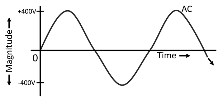
The following graph shows AC current and voltage plotted against time. The positive part of the graph shows voltage and current in the forward direction and the negative part shows current and voltage in the reverse direction.
On the diagram, the curving line showing the AC values is fluctuating between zero and maximum positive and negative values; this shows that the AC voltage and current vary in magnitude.
There are various ways in which polarities are made to exchange positions, one of them is by moving the magnetic field across a conductor.
How AC Voltage and Current are Generated
When the magnetic field produced by a permanent magnet or an electromagnet is moved across a conductor, or a conductor is moved across the magnetic field, voltage is induced in that conductor.
NB - When the magnetic field is moved along a conductor, there is no induced voltage in the conductor.
If a conductor forms a closed circuit, the induced voltage will cause electrons to flow in a conductor, since electrons flow in a complete circuit. This is generally how AC voltage and current are generated.
Have you ever played around with a permanent magnet and noticed that one side of a magnet attracts metals and the other repels metals? This is due to charges on electrons and protons in metals and the effect of the magnetic field.
When a magnetic field is moved across a conductor in one direction, it can first repel electrons, causing the electrons to take a certain direction of flow. When the magnetic field is moved in the other direction, it will attract electrons, causing them to change the direction of flow.
What actually happens when moving a magnetic field across a conductor is that the polarities responsible for the flow of electrons are exchanging positions, resulting in the change in direction of flow of electrons.
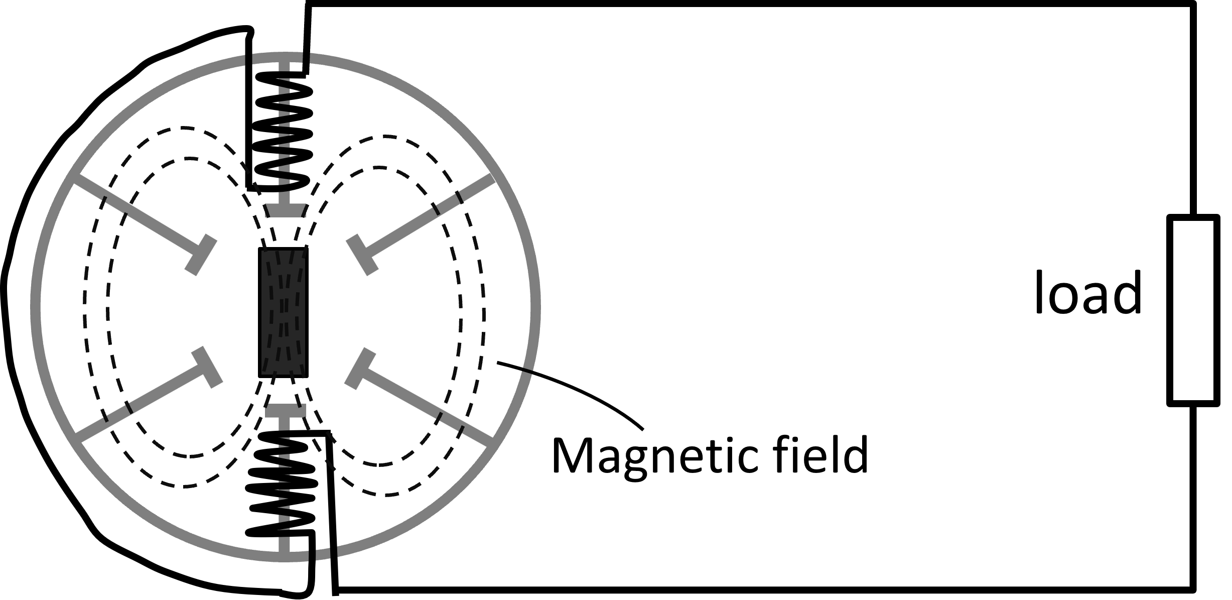
Instead of moving the magnetic field across a circuit conductor, we can rotate the magnetic field covering the circuit conductor coils as shown below. This is how most generators work because the method is cheaper than moving the magnetic field across a conductor.
The coiling of a conductor as shown in the diagram below is to increase the length of a conductor inside the rotating magnetic field. Increasing the length of a conductor inside a magnetic field increases the amount of voltage induced in the conductor.
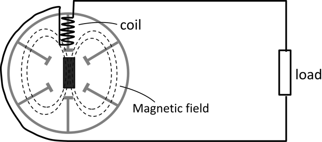
The previous diagram illustrates the structure of an AC generator (alternator). The magnetic field of a generator is made to rotate with the help of steam or water turbines.
Why Do AC Voltage and Current Vary in Magnitude?
What causes the magnitude (amount) of AC voltage and current to vary with time is the amount of magnetic field cutting across a conductor.
When rotating the magnetic field covering stationary conductor coils, at some points there will be no magnetic field cutting across the coils and the induced voltage will be zero.
At some other points the whole magnetic field will be cutting across the conductor coils, and the induced voltage will be at maximum.
Finally, at some other points the magnetic field will be partly cutting across the conductor coils; the voltage induced will be between zero and maximum.
The following waveform is a sinewave that shows the AC values of voltage and current plotted against time.
NB - A waveform is any graph of quantities with values that continually vary with time. A sinewave is an S-shaped waveform graph that AC voltage and current follow when flowing.
As shown in the following AC sinewave graph, in AC we have:
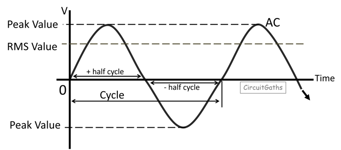
A Cycle
A cycle is a complete rotation of the magnetic field. When the magnetic field covering the coils of a generator rotates back to its initial position, we call that a cycle or one cycle.
The sinewave graph above shows a cycle with a set of complete positive and negative values. The positive half-cycle shows electrons flowing in the forward direction. The negative half-cycle shows a reversal in the flow of electrons.
Periodic Time
Periodic time is the time taken by the magnetic field to complete one cycle. In most generators, the magnetic field completes one cycle in milliseconds
Frequency
Frequency is the number of cycles completed in one second. Frequency is measured in hertz (Hz). Most generators are 50 or 60Hz, meaning that the magnetic field completes 50 or 60 cycles in one second respectively.
AC devices must have a frequency rating that matches the electrical energy supplier's frequency where they are intended to be used, otherwise they may not operate well or may stop working.
Peak Value
On the AC sine wave, the largest value reached by voltage or current in every half cycle is called the peak value.
Root Mean Square Value (RMS Value)
This is the effective value which is generally used to represent the AC voltage and current values.
Whenever the AC quantity is given, it is assumed to be the RMS value.
Since AC voltage and current continually vary in magnitude with time, we can't use the instantaneous values for AC appliances' rating or other purposes. We use the RMS value.
There are several ways of finding the RMS value. If given the peak value, the RMS value can be calculated by dividing the peak value by the square root of two, as shown in the following formula.
R.M.S Value = Peak value ÷ Square root of two
Single and Three-Phase Electricity
Single-phase electricity refers to a system where a generator has one independent coil, with one live conductor supplying electricity to the single-phase loads and a neutral wire returning to the generator from the loads to make the circuit complete as shown in the following diagram.
To increase the length of a conductor inside the magnetic field, another coil is added to the independent coil as shown in the following diagram.
To have more phases, the generator should have independent coils that are placed at a certain angle from each other. In three-phase electricity, the coils are positioned 120° apart as shown in the diagram below.
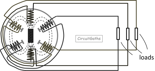
In the previous diagram, we have six conductors. Three are supplying power to the loads and the other three are returning to the generator from the loads to make the circuit complete.
We can reduce the number of conductors by connecting the generator and three-phase loads in either star configuration or delta configuration. Single-phase loads will receive power by connecting them to any phase and the neutral wire that emerges from the star configuration.
Three-phase generators and distribution transformers are usually connected in a star configuration, so that a neutral wire is obtained for single phase loads to be connected.
Star Configuration
A star configuration is when the three live conductors are each connected to a load or coil of a generator and the ends are joined together as shown in the following diagram.
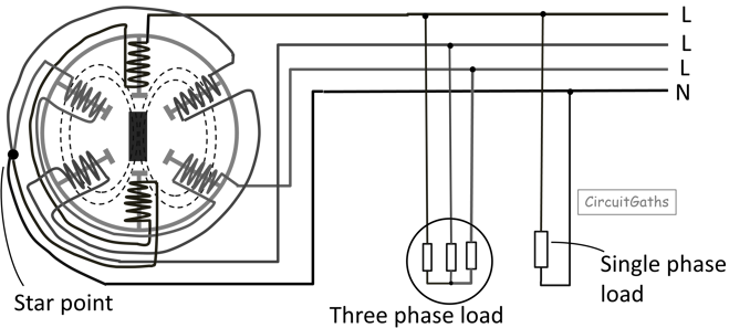
The point where the three live conductors are joined is where the neutral wire emerges.
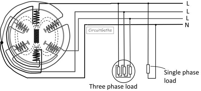
Delta Configuration
A delta configuration is where the three live conductors are each connected to a load and the outlet from each load is connected to the start of another load as shown in the following diagram.
If we measure the voltage between the phase and neutral conductor, the voltage we get is called phase voltage. If we measure the voltage between two live conductors, the voltage we get is called Line voltage.
Phase voltage differs from line voltage. Line voltage is usually higher than phase voltage because on line voltage, we are combining the voltages of two phases.
Line voltage = Phase voltage × Square root of three