What is a Soft Starter and How it Works
A soft starter is a device used to control electric motors; it is designed to start, run and stop electric motors, and more importantly, it smoothly start and stop them.
Electric motors draw a lot of current during starting (inrush current) due to the low impedance (resistance and inductance) of their windings, and this has a significant impact on larger electric motors.
High inrush current causes an electric motor to start with unnecessarily high speeds, resulting in vibration of the equipment and the motor itself, giving them mechanical stress and eventually leading to failure.
While cheaper starters like star-delta starters, can reduce starting current, they are not as effective as soft starters in situations where smooth starting is needed, like when moving a conveyor belt carrying fragile materials.
A soft starter smoothly starts electric motors by initially applying a reduced voltage to the electric motor and gradually increasing the voltage to full voltage.
If voltage is reduced, current is also reduced and the force applied by the motor (torque) will also be low, thereby smoothly starting electric motors.
During stopping, a soft starter gradually decreases the voltage being applied to the motor to zero, and the electric motor smoothly stops.
Soft Starter Construction and Working
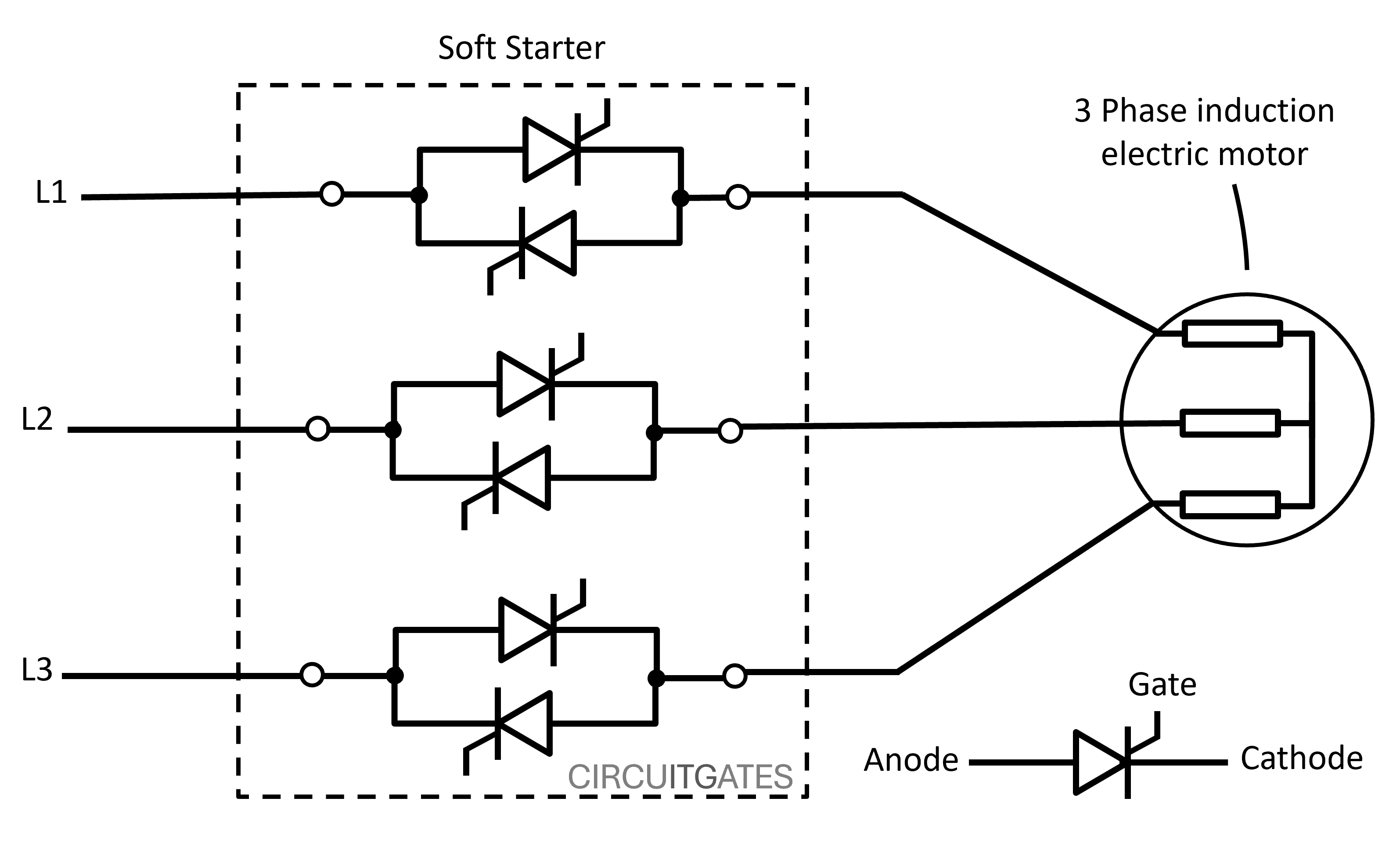
As shown in the previous diagram, a soft starter mainly consists of a pair of anti-parallel thyristors (silicon-controlled rectifiers, SCRs) on each of the three phases.
An SCR or thyristor is a three-terminal semiconductor device that allows current to flow through it in only one direction, just as a rectifier diode, which is why they are connected facing different directions on each phase or in an anti-parallel way, so that AC can flow in the forward and reverse direction.
The device (thyristor) exists in only two states: the ON state and the OFF state. In soft starters, they work as controlled switches to control the AC electric motors.
An SCR is different from a rectifier diode in that, for an SCR to allow current through it (or from anode to cathode), there must be a sufficient voltage, usually of small value, between the gate and cathode to put the SCR in the ON state.
Once an SCR goes into the ON state, the only way to put it into the OFF state is to reduce the supply voltage to zero (the voltage between the anode and the cathode).
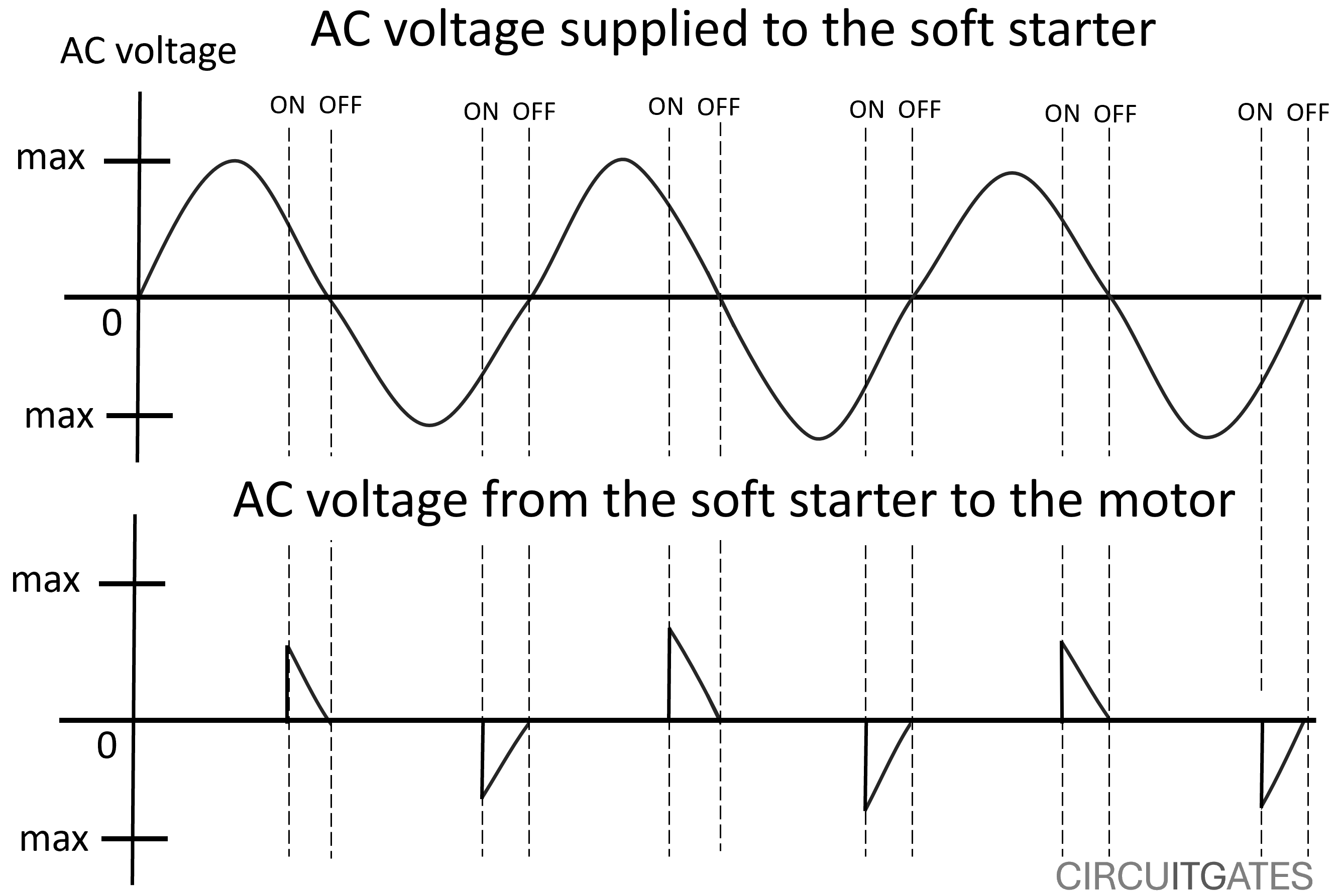
Since the supply in soft starters is AC, which has voltage and current that go from zero to maximum several times in every second, the SCRs are put in the ON and OFF state several times per second
For a soft starter to smoothly start the electric motor, the SCRs are first put into the ON state near the end of every AC half cycle, and this results in a small amount of voltage being applied to the electric motor, as shown in the following diagram.
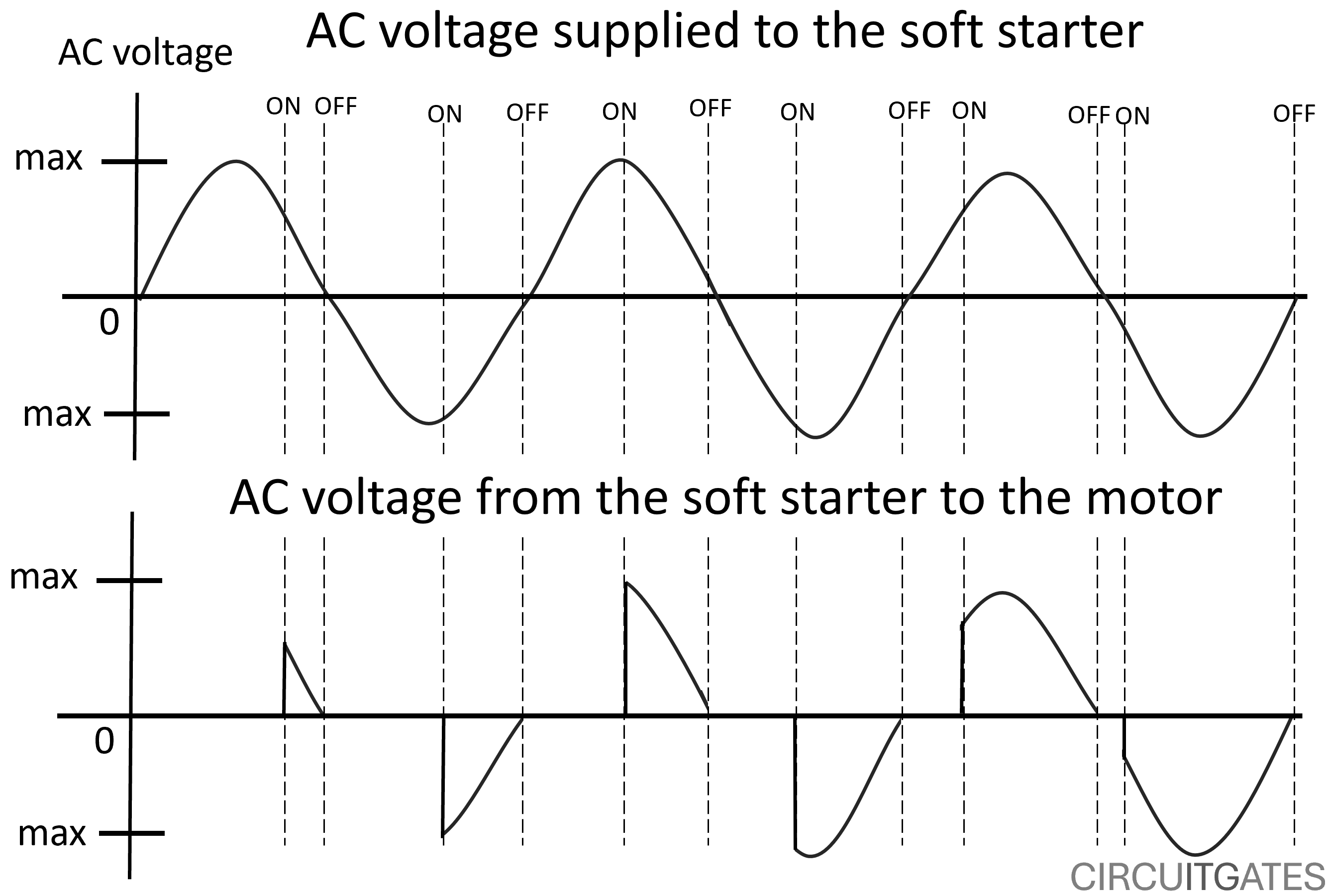
To gradually increase the voltage to the electric motor, the SCRs are put into the ON state much earlier and earlier in the AC half cycles, and this results in an increase in voltage to the electric motor, until the electric motor receives full voltage.
The gate-cathode control path of the SCR is connected to the printed circuit board assembly that controls the ON and OFF states of the SCR based on the parameters set by the operator, such as acceleration time.
Connecting Soft Starters
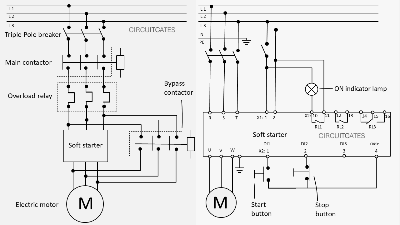
There are several ways in which soft starters are connected; sometimes they feature a main contactor, a separate overload relay, a bypass contactor and other components.
While the soft starter can work properly by just connecting it to the electric motor through the three-phase circuit breaker, as shown in the following diagram, other devices can be added to achieve certain controls.
Soft starters can be installed with a main contactor, a bypass contactor, an overload relay, and others as shown in the following diagram.
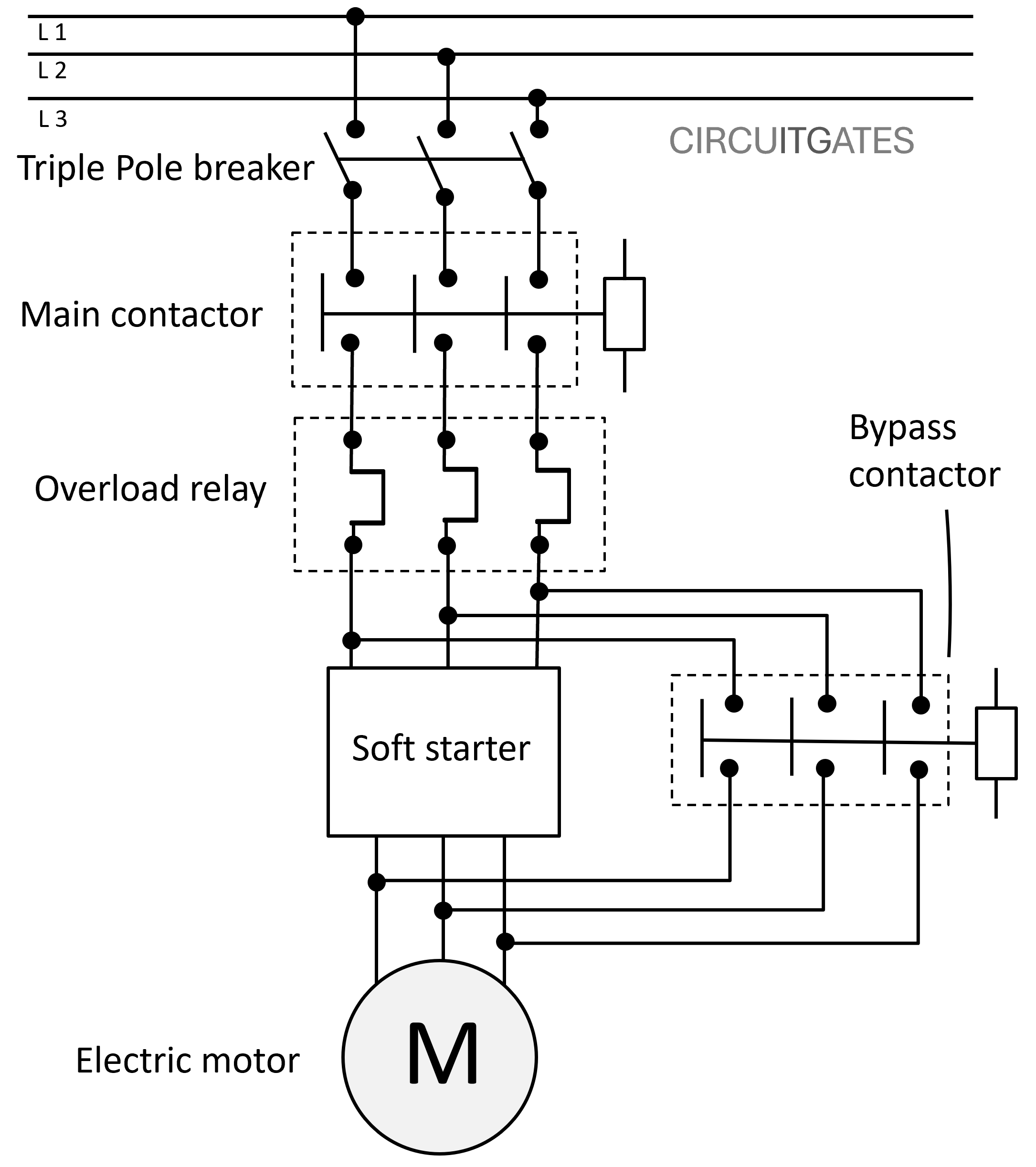
In soft starters, the main contactor provides physical isolation when the starter is not in use and in the event of a soft starter trip.
Electronic components inside a soft starter such as SCRs, do not offer a high degree of isolation because they have a problem of current leakage through them. When the main contactor is used, the electric motor will not automatically start in the event of a stoppage.
A soft starter installed with a bypass contactor is used to reduce the dissipation of heat by thyristors. Electronic components inside a soft starter dissipate heat during running, which can lead to soft starter overheating and failure.
To overcome overheating of soft starters, soft starters are often installed with bypass contactors. Some soft starters have inbuilt bypass contactors. Soft starters with inbuilt bypass contactors don't need an external bypass contactor.
The bypass contactor provides an alternative way to the soft starter for current and voltage to reach the electric motor when the motor reaches full speed or full voltage.
If the soft starter is designed in such a way such that when bypassed through a bypass contactor, its internal overload relay will not be able to do its work, then an external overload relay must be installed.
Controlling the Soft Starter
The control circuit of most soft starters consists of a control supply, digital inputs, digital outputs (output relays), and serial communication protocols that enable sending and receiving of different types of signals that enable the control of soft starters.
For digital inputs, digital outputs, and serial communication protocols to control the soft starter, there are soft starter parameters that first need to be set or programmed, which correspond to these inputs, outputs, and serial communication protocols.
The Control Supply
The control supply part of the soft starter is used to supply voltage to the circuit board, fans, and other components in the soft starter.
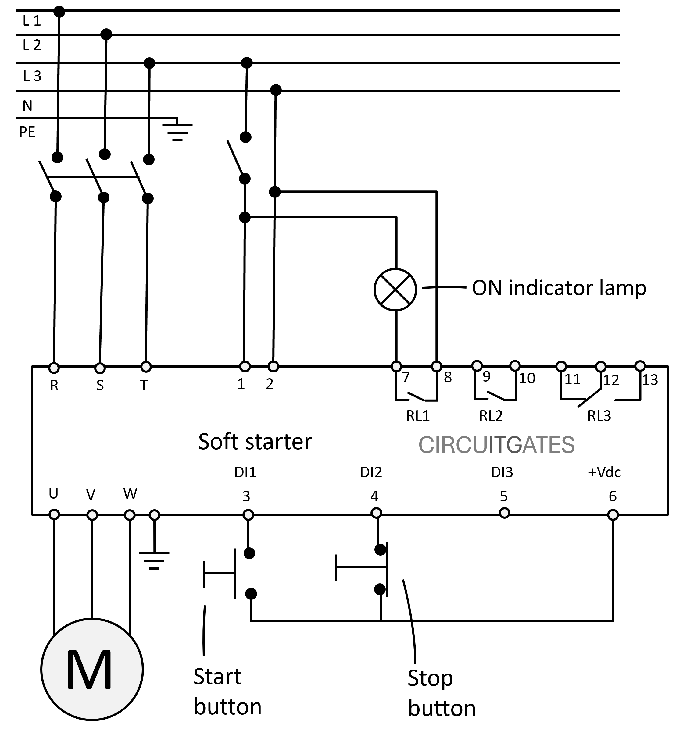
The control supply voltage terminals are usually marked 1 and 2, or A1 and A2. A common voltage for control supply voltage is 100V to 250V AC. In the previous diagram we have used a supply of 230V.
Some soft starters have no external control supply terminals; their control is internally supplied.
Digital Inputs - DI1, DI2, DI3
These are inputs that receive individual (discrete) signals that are either ON or OFF (binary 0 or 1) from devices such as start and stop buttons.
When parameters corresponding to these digital inputs are set, they can be used to control various functions of the soft starter such as switching the soft starter ON and OFF, as in the previous diagram.
Digital Outputs (Output Relays - RL1, RL2 )
These are outputs that send individual (discrete) signals that are either ON or OFF (binary 0 or 1) to external devices like indicator lamps and solenoid valves.
In soft starters we often find output relays used as digital outputs. Soft starter output relays can be programmed to close if the soft starter is switched ON, enabling an external circuit connected through it to operate.
For example, on some soft starters, RL1 can be programmed to activate an external bypass contactor when the motor starts to receive full voltage.
Serial Communication Protocols
Serial communication protocols involve the use of PLCs and remote HMIs (touch screens or screens with a keypad, usually installed on the panel door containing the soft starter) to control the soft starter.
Some common types of serial communication protocols include Fieldbus, Ethernet, and Wireless.
Soft Starter Programming
Programming involves setting of soft starter parameters for the soft starter to suit specific electric motor applications.
To set parameters for the soft starter, you need to have its user manual guide, since different brands of soft starters differ slightly on how they are programmed.
There are several parameters that need to be set so that the soft starter matches the specific electric motor applications, and also to enable the operation of the soft starter through digital inputs, analogue inputs, and serial communication protocols.
Some of the areas where parameters need to be set include:
Electric Motor Starting and Stopping
In soft starters, the electric motor can be started using the soft starter keypad (local HMI), PLC (through serial communication protocol), and external start and stop buttons (through digital inputs).
The soft starter needs to be programmed based on which of the previous methods of starting the electric motor is going to be used in starting and stopping of the electric motor.
In the previous soft starter power and control circuits diagram, we have used the external start and stop buttons connected through digital inputs DI1 and DI2 from the internal 24Vdc supply terminal.
Some soft starters have no internal 24Vdc supply, and in that case, an external 24Vdc supply is needed.
For one of the WEG soft starters we have worked with, to use external start and stop buttons wired through digital inputs DI1 and DI2 to start and stop the electric motor (three-wire control), we first go to parameter 61 (P61) and set it to OFF (P61 = OFF)
When the P61 parameter programmed to ON (P61 = ON), the electric motor can only be started and stopped via the soft starter keypad and serial communication protocol only.
And we then go to parameter (P53) and set it to OFF, to allow ON and OFF from two digital inputs (DI1 as start input and DI2 as stop input). Without setting this parameter, the ON and OFF were only from DI1 (two-wire control).
Starting voltage - Usually found in P1 for most soft starters, this sets the starting voltage that will be applied to the electric motor.
Acceleration time - Usually found in P02 for most soft starters, this sets the time for the voltage increment to full voltage.
Soft starter current limitation - allows the maximum current value that can be supplied to the electric motor to be set.
If you have made it this far, you have made it. Consider visiting our YouTube channel; we have helpful electrical tutorials there.