What is a Variable Frequency Drive and How it Works
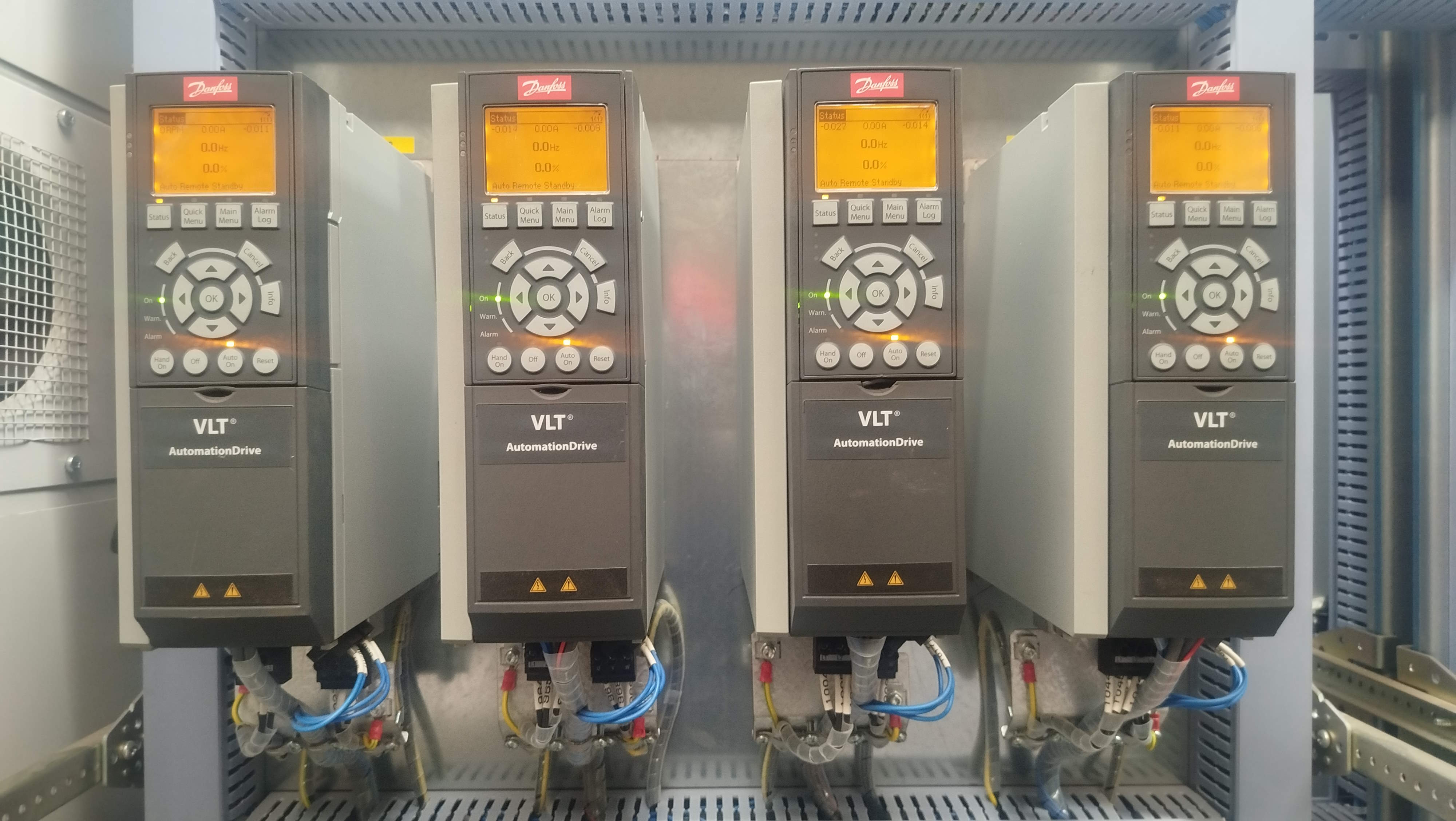
A variable frequency drive is a device used to control AC three-phase induction electric motors.
The VSD is used to start and stop electric motors, and more importantly vary the speed of the electric motor for smooth starting, stopping and running.
A variable frequency drive is also called a variable speed drive.
The term variable speed drive is a generic term that represents devices used to adjust the speed of electric motors or the equipment driven by the motor. These devices can be either electrical or mechanical.
Unlike other starters like soft starters and star-delta starters, a variable frequency drive can change the speed of an electric motor while the electric motor is running.
How a Variable Frequency Drive Varies the Speed of the Electric Motor
A variable frequency drive varies the speed of an electric motor by changing the frequency and voltage of electricity supplied to it or going to the electric motor.
In AC electricity, frequency affects the speed of the electric motor. Higher frequencies cause an electric motor to rotate fast, whereas lower frequencies cause it to run slow.
For a variable frequency drive to vary the speed, it first converts AC to DC and then DC back to AC with an adjustable frequency.
The variable frequency drive has three main parts: the first part that converts AC to DC, the second part that smooths the rectified DC and the third part that converts DC back to AC with an adjustable frequency.
VSD Construction and Working
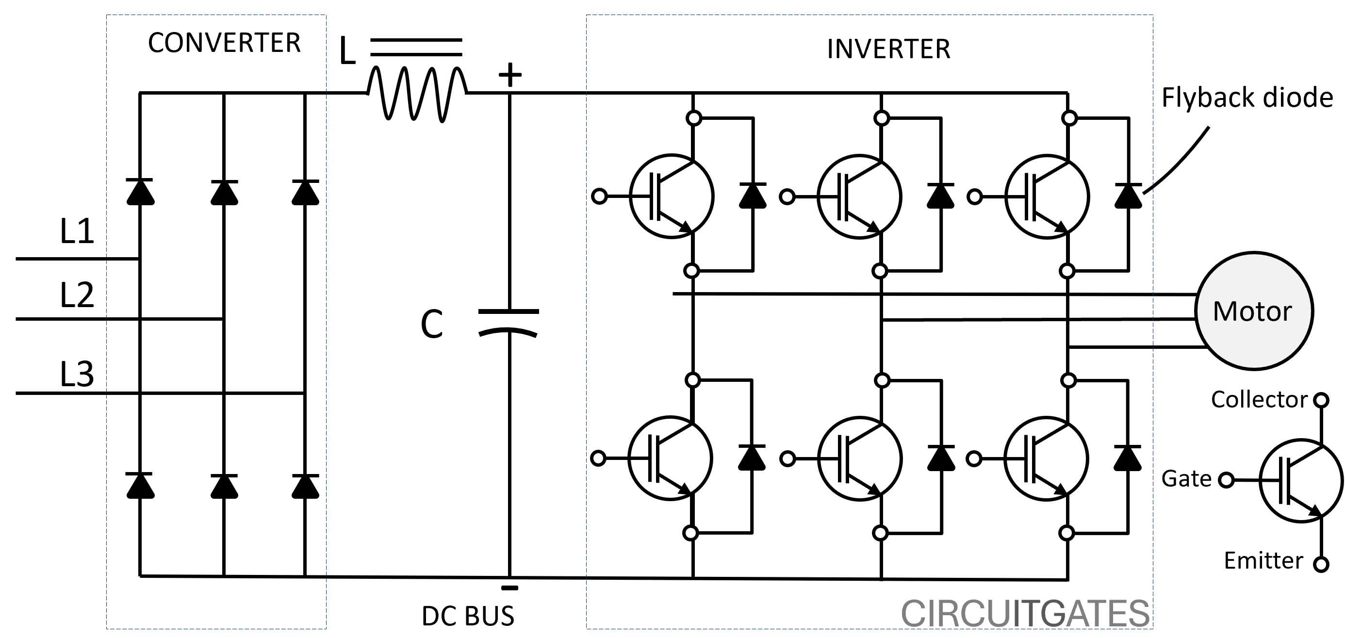
A variable frequency drive consists of a converter (rectifier), a DC bus (filter), and an inverter.
Converter/Rectifier
The rectifier is the part of the VFD that converts AC to DC.
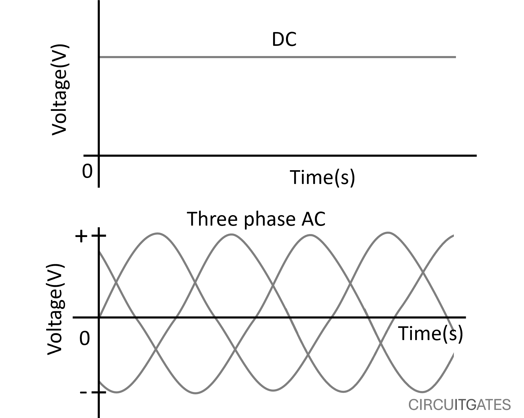
AC is electricity with voltage and current that vary in magnitude and change direction, while DC has voltage and current that flow in the same direction with a constant magnitude, as shown in the following diagrams.
The rectifier part of the VFD consists of diodes that allow current to pass through them in one direction.
These diodes are wired so the output from the rectifier is voltage and current flowing in the same direction from an input of voltage and current that change direction, as shown in the following diagram.
In single-phase VFDs, a full-wave diode rectifier can be used to convert AC to DC.
In three-phase VFDs, each phase is connected between two diodes facing the same direction, as shown in the previous VFD construction diagram.
The diodes after the phases of the three phases are joined together, forming the DC live wire, and the other diodes before the three phases are joined together to form the DC neutral wire.
DC Bus - Filter
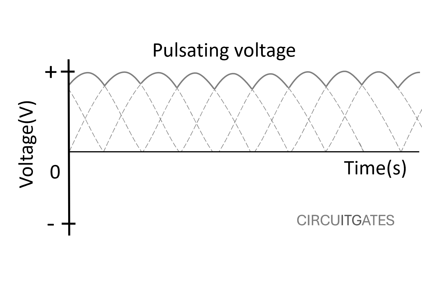
The output from the rectifier is voltage flowing in the same direction but varying in magnitude (pulsating voltage), since the rectifier only allows AC current and voltage to flow in the same direction.
The DC bus, or filter, is the part that smooths the DC rectified voltage to produce a smooth DC voltage, as shown in the following diagram.
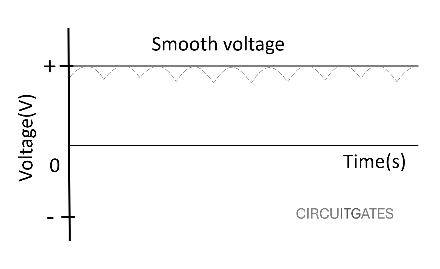
This part consists of devices such as capacitors that store electrical energy and release it when there are fluctuations in the voltage, producing a smooth DC voltage.
Inverter
The inverter is the part that converts DC back to AC, but now in a way that its frequency can be varied between minimum and maximum values, enabling control of the speed of electric motors.
The modern inverter part usually consists of insulated gate bipolar transistors (IGBTs), which are well known for their ability to switch ON and OFF several thousand times per second.
In the inverter part of VFDs, IGBTs are wired in the same way as the previous six diodes of three-phase VFDs. The IGBTs are also connected to the controller, which tells them to switch on and off.
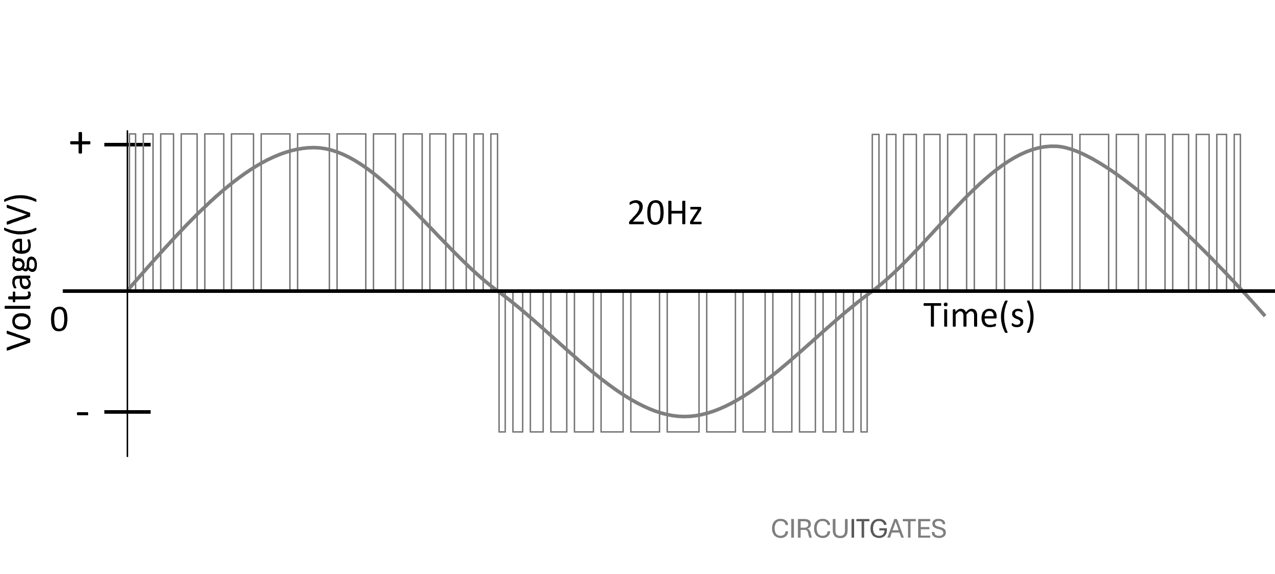
To invert DC to AC or to form every AC half cycle, the IGBTs are controlled to switch on and off several times, with the pulses being small at the start and end of every cycle and increasing towards the middle of the cycle (pulse width modulation), as in the following diagram.
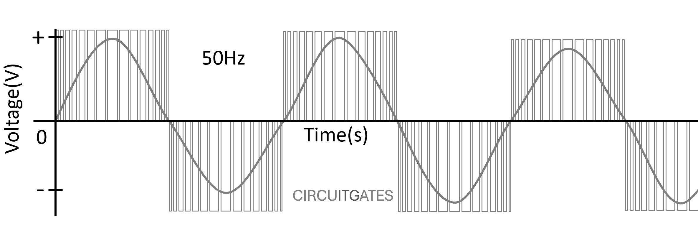
The frequency is varied by changing the length of half-cycles of AC voltage. Frequency is the number of cycles completed per second.
When the length of half cycles or cycles is increased, the number of cycles in every second is reduced, thus reducing the frequency and speed of electric motors.
VSD Power and Control Circuits
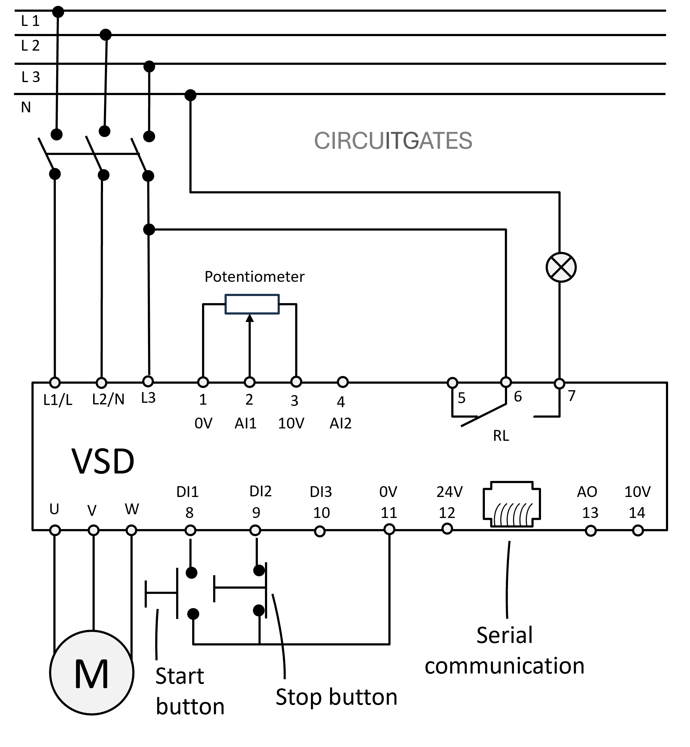
The power circuit of most VFDs, consists of either three phases or single phase and the earth wire, connected to the power input of the VSD (L1/L, L2/N, L3).
The output part of the power circuit from the VFD (U, V, W) consists of three phases and an earth wire, connected to the electric motor.
The control circuit of the VFDs consists of digital inputs, analogue inputs, digital outputs, analogue outputs, relay outputs, and serial communication protocols that enable sending and receiving of different types of signals that enable control of VFDs.
For inputs, outputs, and serial communication protocols to control the VFD, there are VFD parameters that first need to be set (programmed), which correspond to these inputs, outputs, and serial communication protocols.
Digital Inputs - DI1, DI2, DI3
These are inputs that receive individual (discrete) signals that are either ON or OFF (binary 0 or 1), from devices such as start and stop buttons.
When parameters corresponding to these digital inputs are set, they can be used to control various functions of the VFD, such as switching the electric motor ON and OFF, and changing the direction of the electric motor.
Analogue Inputs - AI1, AI2
These are inputs that receive continuous signals, such as current (4-20mA) or voltage (0-10V), from devices like potentiometers and sensors.
When parameters corresponding to these analogue inputs are set, they can be used to control various functions of the VFD, such as the VFD output frequency.
Digital Outputs (Relay outputs - RL1, RL2 )
These are outputs that send individual (discrete) signals that are either ON or OFF (binary 0 or 1) to devices like indicator lamps, external control relays, and solenoid valves.
Digital outputs are used to send signals to external devices. In VFDs, we often find relays (RL) used as digital outputs.
VFD relays can be programmed to close if the VFD is switched ON, enabling devices connected through them to operate, like indicator lamps that give a running signal of the VFD.
Analogue Outputs - AO
These are outputs that send a continuous signal, such as current (4-20mA) or voltage (0-10V), to devices like analogue meters.
Just like digital outputs, the analogue outputs are used to send out signals to external devices. In most cases, VFD analogue outputs are used as inputs to other devices like PLCs.
Serial Communication Protocols
Serial communication protocols enable the use of PLCs and remote HMIs (touch screens or screens with a keypad, usually installed on the panel doors containing VFDs) to control VFDs.
Some common types of serial communication protocols include Fieldbus, Ethernet and Wireless.
VFD Control and Programming
VFD programming involves the setting of VFD parameters for the VFD to suit specific electric motor applications.
To set parameters for VFDs, you need to have its user manual, since different brands of VFDs differ slightly on how they are programmed.
There are several VFD parameters that need to be set so that the VFD matches the specific electric motor applications and also to enable the operation of the VFD through digital inputs, analogue inputs, and serial communication protocols.
Some of the areas where parameters need to be set include:
Starting and Stopping of the Electric Motor
In VFDs, the electric motor can be started using the VFD keypad (default), PLC (through serial communication protocol or digital inputs), and external start and stop buttons (through digital inputs).
The VFD needs to be programmed according to which method of starting and stopping will be used to control the electric motor.
In the previous VFD power and control circuit diagram, we used the external start and stop buttons connected through digital inputs.
Frequency Control
Just like the previous starting and stopping of the electric motor, the frequency of electricity going to the electric motor can be controlled or adjusted through the VFD keypad, PLC (serial communication protocol or analogue inputs), and potentiometer (through analogue inputs).
The VFD needs to be programmed based on which of the previous references for adjusting the frequency of the electric motor will be used.
In the previous VFD power and control circuit diagram, we used a potentiometer connected through analogue inputs to adjust the frequency.
Minimum frequency - The VFD needs to be set to the lowest frequency at which the VFD can operate the electric motor.
Maximum frequency - The VFD needs to be set to the highest frequency at which the VFD can operate the electric motor.
Acceleration time - The VFD needs to be set to the time the electric motor takes to reach the setpoint speed from a lower starting speed.
Motor current limit - The VFD needs to be set to the maximum current that it will allow to flow to the electric motor.
If you have made it this far, you have made it. Consider visiting our YouTube channel; we have helpful electrical tutorials there.